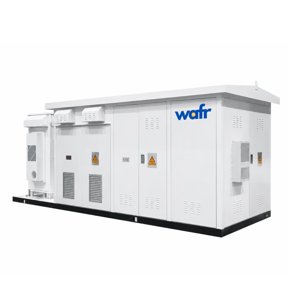
PRODUCT PREVIEW
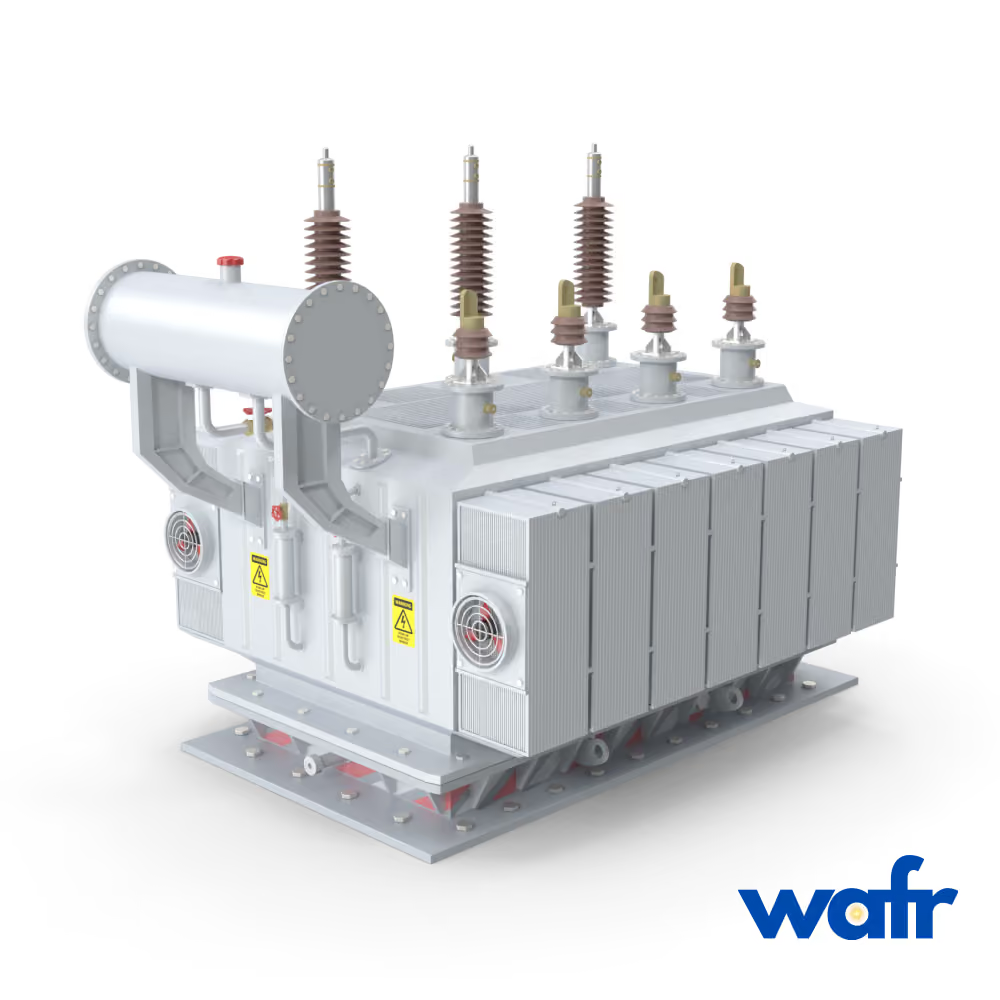
Transformers
Project-specific power transformation
https://cdn.prod.website-files.com/6a838ff6d7b603ad9aeaed44/6a90ca97cceb3cdd72f3cfb3_wafr_dry_coolers_hero.mp4
Wafr Equipment
Under Development
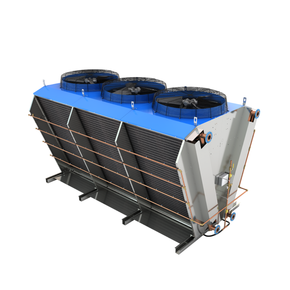
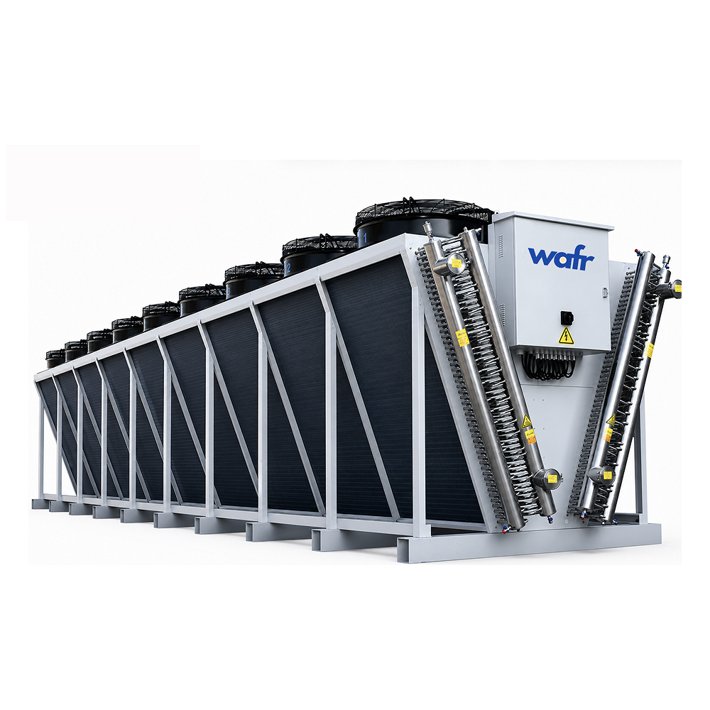
V-shape and flat-shape dry coolers with adiabatic pad and spray-system options, engineered around climate, ambient conditions and project load.
Overview
Wafr supplies air-cooled and adiabatic dry cooler systems for data centre, industrial, commercial, and critical infrastructure applications. Available configurations include V-bank and flat-bed arrangements, with optional adiabatic pad or spray-assisted cooling for applications requiring additional heat rejection during higher ambient temperatures.
Systems can be configured for water, ethylene glycol, and propylene glycol loops, with coil materials, casing, fans, controls, noise requirements, and overall equipment configuration selected around the thermal duty and site conditions. Wafr can also support packaged and containerized heat-rejection systems for projects requiring modular deployment, high cooling capacity, or integration into constrained sites.
CONFIGURATION
V-bank / Flat-bed
WORKING FLUID
Water / Ethylene Glycol / Propylene Glycol
HEAT EXCHANGER AREA
120 to 5,100 m²
Fan options
AC / EC
Fan Diameter
200 to 1,800 mm
https://cdn.prod.website-files.com/6a838ff6d7b603ad9aeaed44/6aa2f5b61f05ba4509cf14d4_wafr_dry_coolers_capabilities_video_v2.mp4
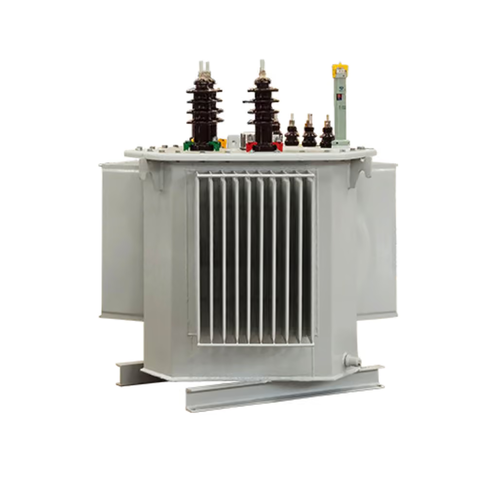
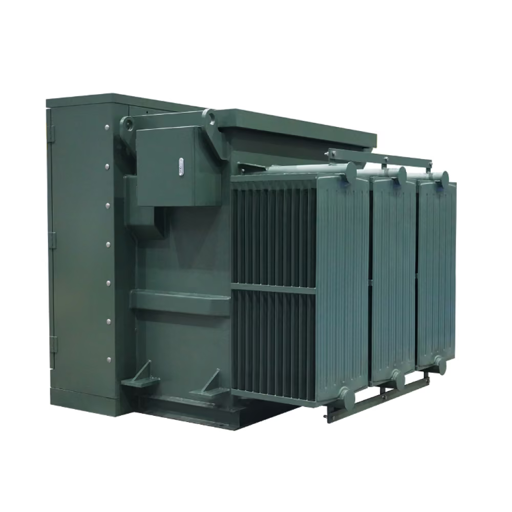
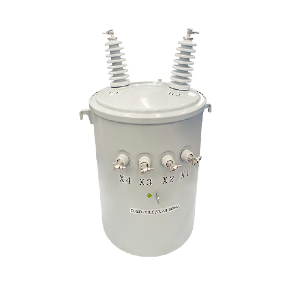
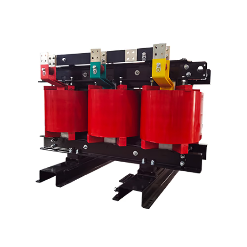
Four distribution transformer platforms engineered for Wafr's project scope.
Five switchgear platforms engineered for Wafr's project scope.
Engineering
Cooling capacity and equipment sizing are determined based on design temperatures, ambient conditions, fluid selection, required approach, and project-specific heat rejection requirements.
Structured so engineering and procurement teams can review key ranges quickly.
Fluid Coolers
470 – 2,190 kW · 756–6,811 m²
Freon Condensers
343 – 2,005 kW · R404A
Ammonia Condensers
420 – 2,237 kW · NH3
CO2 Gas Coolers
407 – 1,267 kW · 94 Bar
Oil Coolers
240 – 1,309 kW · ISO VG 46
Fin Spacing
1.8 – 3.2 mm
Container Footprint
AC / EC / marine / explosion-proof
Fan Options
AC / EC / marine / explosion-proof
Three-Phase Oil-Immersed
oil-immersed
transformers
Fluid Coolers
fluid-coolers
dry-coolers
WTB Commercial
wtb-commercial
thermal-storage-battery
Three-Phase Dry-Type
dry-type
transformers
Freon Condensers
freon-condensers
dry-coolers
Single-Phase Pole-Mounted
pole-mounted
transformers
Ammonia Condensers
ammonia-condensers
dry-coolers
Pad-Mount
pad-mount
transformers
CO2 Gas Coolers
gas-coolers
dry-coolers
Oil Coolers
oil-coolers
dry-coolers
Capacity Range
Working Fluid / Medium
Fin Spacing
Container Footprint
Fan Options
50–500 kVA
11 / 0.433 kV
Dyn11
ONAN
IEC 60076
oil-immersed
30–800 kVA
10 / 0.4 kV
Dyn11
AN / AF
IEC 60076-11
dry-type
15–100 kVA
13.2 / 0.24 kV
—
ONAN
IEC 60076
pole-mounted
4,000 kVA
26–36 kV / 34.5 kV rated
Dyn11
ONAN
UL 1561 / IEEE C57.12
pad-mount
470–2,190 kW
Water / Glycol
1.8–3.2 mm
20 ft (6,058 mm) / 40 ft (12,192 mm)
AC / EC / marine / explosion-proof
fluid-coolers
343–2,005 kW
R404A
1.8–3.2 mm
20 ft (6,058 mm) / 40 ft (12,192 mm)
AC / EC / marine / explosion-proof
freon-condensers
420–2,237 kW
NH3
1.8–3.2 mm
20 ft (6,058 mm) / 40 ft (12,192 mm)
AC / EC / marine / explosion-proof
ammonia-condensers
407–1,267 kW
CO2 (94 Bar)
1.8–3.2 mm
20 ft (6,058 mm) / 40 ft (12,192 mm)
AC / EC / marine / explosion-proof
gas-coolers
240–1,309 kW
ISO VG 46 oil
1.8–3.2 mm
20 ft (6,058 mm) / 40 ft (12,192 mm)
AC / EC / marine / explosion-proof
oil-coolers
Maximum nominal cold storage capacity
kWh(th)
1,500
1,000
500
wtb-commercial
630–1,250 kVA
11 / 0.433 kV
Dyn11
ONAN
IEC 60076
oil-immersed
1,000–2,500 kVA
10 / 0.4 kV
Dyn11
AF
IEC 60076-11
dry-type
15–150 kVA
23/33 kV / 0.24 kV
—
ONAN
IEC 60076
pole-mounted
5,000–7,250 kVA
11–17 kV
Dyn11
ONAN / ONAF
UL 1561 / IEEE C57.12
pad-mount
1,600–4,000 kVA
33 / 0.69 kV
Dyn11
ONAN
IEC 60076
oil-immersed
Phase-change temperature
°C
Grade C7: 7.5 ± 1 · Grade C18: 18 ± 1
Grade C7: 7.5 ± 1 · Grade C18: 18 ± 1
Grade C7: 7.5 ± 1 · Grade C18: 18 ± 1
wtb-commercial
5,000–8,800 kVA
34.5 / 0.48 kV
Dyn11
ONAN / ONAF
IEC 60076
oil-immersed
Charging water inlet temperature
°C
C7: 5 · C18: 15
C7: 5 · C18: 15
C7: 5 · C18: 15
wtb-commercial
Discharge outlet temperature
°C
C7: 7–12 · C18: 18–23
C7: 7–12 · C18: 18–23
C7: 7–12 · C18: 18–23
wtb-commercial
Peak discharge temperature
°C
C7: 16.8 · C18: per test report
C7: 16.8 · C18: per test report
C7: 16.8 · C18: per test report
wtb-commercial
Storage method
—
Latent (phase change)
Latent (phase change)
Latent (phase change)
wtb-commercial
Rated flow rate
m³/h
58
40
20
wtb-commercial
Water supply pipe diameter
DN
150
150
100
wtb-commercial
Working pressure
MPa
0.8–1.0
0.8–1.0
0.8–1.0
wtb-commercial
Pressure drop
kPa
76.8
65.7
50.7
wtb-commercial
Recommended pipe velocity
m/s
0.8
0.8
0.8
wtb-commercial
Recommended chiller capacity
kW
Per configuration
142–165
70–80
wtb-commercial
Recommended charging window
h
≈ 8 (off-peak / valley tariff)
≈ 8 (off-peak / valley tariff)
≈ 8 (off-peak / valley tariff)
wtb-commercial
Recommended discharge window
—
Local peak tariff hours
Local peak tariff hours
Local peak tariff hours
wtb-commercial
Control
—
Networked automatic program control
Networked automatic program control
Networked automatic program control
wtb-commercial
Unit size (L × W × H)
mm
9,300 × 2,896 × 3,170
6,800 × 2,896 × 3,170
3,808 × 2,896 × 3,170
wtb-commercial
Operating weight
kg
≥ 36,000
≥ 26,500
≥ 14,300
wtb-commercial
Dry cooler systems can be configured with a range of casing, coil, fin, fan, and control options to suit project-specific thermal, environmental, and operating requirements.
Available construction options may include galvanized or stainless steel casings, along with a range of fin and tube material selections based on corrosion resistance, durability, and application needs.
Optional adiabatic pad or spray-assisted cooling can be incorporated for applications requiring additional heat rejection at higher ambient temperatures. Systems can be configured for water, ethylene glycol, or propylene glycol service.
Controls and accessories can be selected based on the project scope and may include AC or EC fans, junction boxes, control cabinets, inverter control, filtration, access doors, and other application-specific features.
Compliance
CSA
Applicable by configuration
UL / cUL
Applicable by configuration
IEEE
Applicable by configuration
ANSI
Applicable by configuration
NEMA
Applicable by configuration
QA Docs
Applicable by configuration
Quality Commitment
24 months warranty against manufacturing defects, counted from commissioning (or 30 months from shipment, whichever ends first)
Covers transformer core, windings, tank and factory-installed components
Defective units repaired or replaced at Wafr's cost, including freight
Technical support: remote diagnosis within 48 hours, on-site service available for major claims
Spare parts shipped within 30 days for standard models
Extended warranty and preventive-maintenance packages available on request
Final warranty terms per purchase contract.
Resources
Everything an engineer or procurement team needs to move from evaluation to specification.
Specify
Dry Coolers
for your project
Send Wafr your project requirements and the team can confirm fit, configuration and documentation.